TV Tuner

About
TV Tuner is an add-in for ActiveView2 (AV2) to help measure and optimize the single pulse response (SPR) of the system.
How it works
TV Tuner is centered around the concept of Procedures, which serve as organized sets of instructions for data collection and analysis. Within each Procedure are Steps, encompassing specific parameter ranges and settings to acquire and analyze. These Steps are further broken down into Results, representing distinct combinations of parameters.
The software utilizes this information to generate patterns in AV2 corresponding to each Result. When a Procedure is run, these patterns are executed sequentially, with inter-step delays to accommodate for cell pressure stabilization during gas flow changes.
Automatic data collection functionality retrieves, processes, and displays data in real-time as the Procedure progresses. Alternatively, manual data retrieval is possible, allowing users to assign data to entire Steps or individual Results as needed.
When the data for a Result become available, data processing, facilitated by iolite, occurs behind the scenes, analyzing peak locations and various statistical measures of the SPR.
Upon completion of a Procedure, suggested parameters are provided for each Step, though users can exercise their analytical discretion when choosing the best combination of parameters.
Results can be stored in a Library for future reference, and the software offers options to email or create a zip file containing Procedure details, data, and SPR measurements.
Installation
Note
TV Tuner requires AV2 version 1.5.1.33 or later (pipeline 1.0.0.5) and iolite 4.9.0 or later.
On Nu Vitesse Systems
A comprehensive guide to setting up the Vitesse and laser system is available for download here.
Method, sequence and batch templates can be found here.
All Other Systems
Obtain the TV Tuner installer from the iolite store
Run the installer on your AV2 computer
Activate the add-in using AV2's settings ( button, bottom left) → Manage Addin
Install and register iolite 4 on the AV2 computer (see the iolite installation guide for details)
Import a file from your mass spectrometer in iolite to be sure that, for example, the timestamp format is set and iolite is able to import your mass spectrometer files
TV Tuner can automatically receive data from the mass spectrometer in three ways: using the Chronicle File Watcher (CFW), a built-in file watcher, or the icpTOF web service. For more information about CFW or the icpTOF web service, see the AV2 manual or contact Tofwerk, respectively.
Note
If you are using a Nu Vitesse system, please see the section on Nu Vitesse for additional setup requirements.
User interface
The TV Tuner user interface is divided into four tabs: Tune, Library, Editor, and fa:cog Settings.
Tune
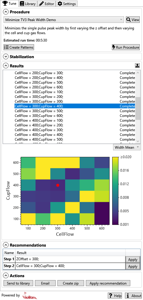
Fig. 37 The Tune tab
The Tune tab consists of 5 sections:
- Procedure
This section is where you can select a Procedure, create AV2 laser patterns for the selected Procedure, and run the created patterns.
- Stabilization
This section is where you can view the cell pressure as a function of time. This can be helpful to visually validate your selected stabilization criteria (see fa:cog Settings).
- Results
This section is where SPR information will be visualized as the data become available and are processed by iolite. If a Step consists of a single variable parameter, the Results will be visualized as a statistical plot, whereas if the Step consists of two variable parameters, the Results will be visualized as a heatmap (shown in Fig. 37).
- Recommendations
This section considers all of the results for each Step and suggests a parameter combination deemed optimal. If targeting peak width, it is calculated as the minimum (or maximum) peak width while also maintaining greater than the median peak height.
- Actions
This section allows you to send the current run to the Library, via email, or to a zip file. It also allows you to apply all recommendations via a single button.
Note
Each section can be expanded or collapsed as needed by clicking the round arrow button to the left of the section name.
Selecting and running a procedure
The active Procedure is selected via the combo box in the Procedure section. This combo box will contain the built-in procedures as well as any custom procedures you have created (see Editor).
TV Tuner comes with three built-in Procedures:
- Current Single Pulse Response
Creates a single tuning ablation line that can be used to determine the current SPR for the current laser conditions.
- Minimize TV3 Peak Width
A two-Step Procedure that first optimizes the Z-offset (step 1) and then optimizes the cup and cell flow rates (step 2) for minimum peak width.
- Maximize TV3 Peak Height
A two-Step Procedure that first optimizes the Z-offset (step 1) and then optimizes the cup and cell flow rates (step 2) for maximum peak height.
Clicking the View button beside the combo box will take you to the Editor tab where you can view and edit the selected Procedure's details.
Note
Built-in Procedures cannot be edited. You can copy a built-in Procedure to create a custom version that can be edited.
Beneath the combo box is a description of the selected Procedure. This description can be edited in the Editor tab. The estimated run time for the Procedure is also shown. The estimate is calculated based on the laser pattern durations and the estimated cell pressure stabilization time.
Once you have selected the Procedure you want to run, you can create the patterns (tuning ablation lines) required for the Procedure by clicking the Create Patterns button. The patterns will be created at the current stage position. You should position these patterns over your tuning sample so that they avoid any surface areas that may cause signal anomalies.
Once your patterns have been created, the Steps for the Procedure are added to the Results section of the Tune tab. Expanding each Step will show the Result (ablation line) associated with each combination of tuning parameter values. Initially each Step and Result will have a status of 'Waiting'.
When you are ready to run the Procedure, click the Run Procedure button. Ablation of each line will begin after the tuning parameters have been set and the cell pressure has stabilized (Fig. 38). The stabilization plot can optionally show the slope of the cell pressure versus time for the last 15 seconds. The stabilization criteria can be set in the fa:cog Settings tab.
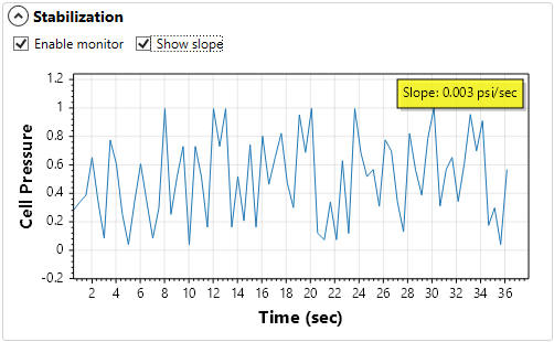
Fig. 38 The Stabilization section of the Tune tab
If one of the automatic data collection mechanisms is enabled, the data for each tuning line will be retrieved and processed after each line is finished. The status for each result will change from 'Acquiring' to 'Processing' to 'Complete' as iolite reads in the data and determines the SPR for the data. If there is an error with processing the data, the status will change to 'Error'. If you are not using automatic data collection (see Editor), a Select Data button will be shown in the Results section of the Tune tab. Clicking this button will allow the analyst to select a file containing all the tuning data. Alternatively, you can right click on a specific Step or Result and select 'Select Data' from the context menu to assign a file to that specific part.
Once some data have been received, clicking on the Step in the Results section will plot a summary of the SPR data for that Step. If the Step contains just one parameter being adjusted, the plot will show the selected SPR metric (e.g., Width Mean) vs the parameter being adjusted (Fig. 39). If the Step contains two variable parameters, the plot will be a heatmap showing the selected SPR metric as a color versus the parameters being adjusted (Fig. 40). If you let the mouse linger over a point in the heatmap, a tooltip will show the data for that specific result.
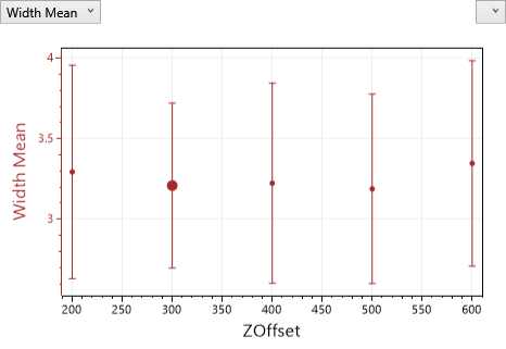
Fig. 39 The Results plot showing a single parameter tuning Step
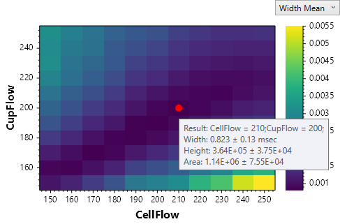
Fig. 40 The Results plot showing a two parameter tuning Step
For single parameter Steps (e.g., optimizing the Z-offset) you can adjust which SPR metric (peak width, height or area) is being displayed in the plot by clicking the dropdown menu to the top left (for the left axis) or the top right (for the right axis). Similarly, selecting a metric from the dropdown menu to the top right of the heatmap will change which parameter is visualized.
Double-clicking on any tuning result in the Results plot or on the name of a tuning line in the list of Results, will open a window showing more details about that tuning line (Fig. 41).
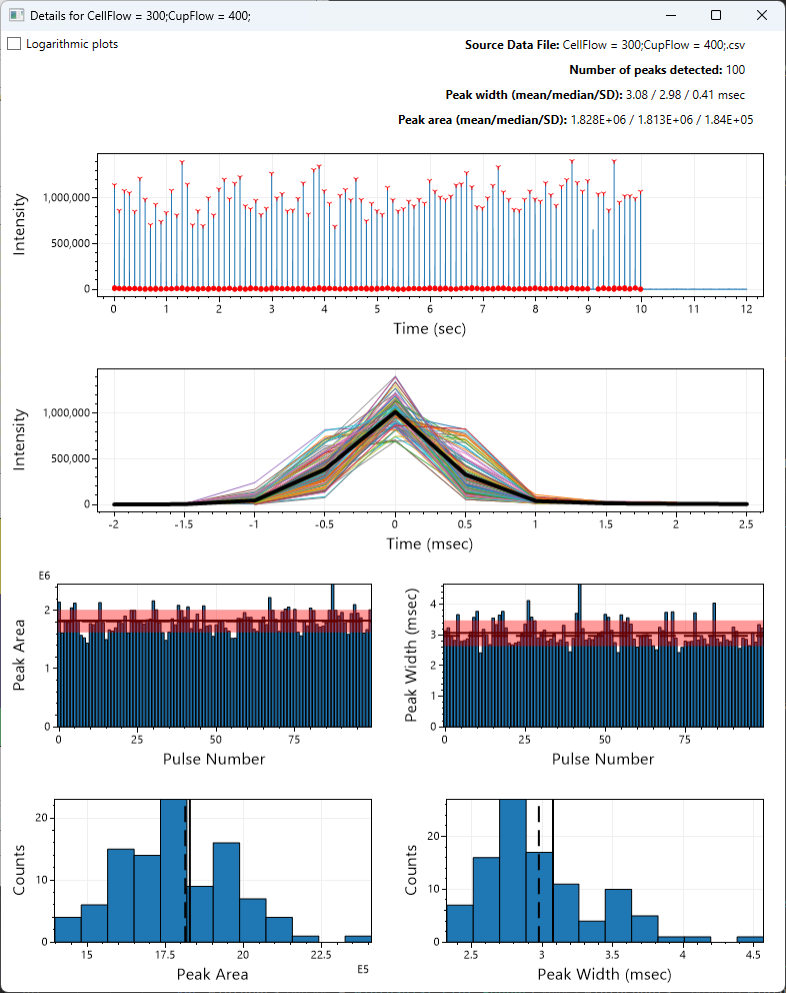
Fig. 41 Detailed information regarding the SPR analysis for one Result
In the Details window, the top-most plot shows where the peaks were found, with the location of the peak max shown as a red 'v', and the position at which the width was measured marked by red filled dots. The second from top plot shows the mean peak superimposed on top of each individual peak. The third from top plots show the peak area and width (including standard deviation shaded in red) in pulse order to show if these values are evolving within a tuning line. The bottom row shows histograms of the area and width to help describe the variation in these values. All plots can be zoomed using the mouse wheel or right-clicking + dragging, and panned by left-clicking + dragging. Additionally, the plots can be rescaled, copied or saved using a right-click context menu.
If you are running a multi-step procedure, a small dialog will popup between steps that allows you to apply the recommended parameters, another set of parameters of your choosing or to move on to the next step without making any changes.
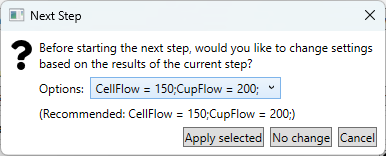
Fig. 42 The dialog that appears between steps in a multi-step procedure
Library
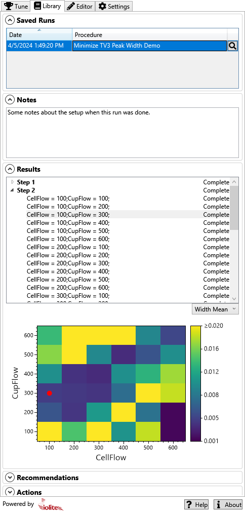
Fig. 43 The Library tab
The Library tab consists of 5 sections:
- Saved Runs
This section lists all the previously-run and saved Procedures. Clicking on a an entry in the table will display the associated notes, results, and recommendations.
- Notes
This section allows you to add notes to a saved run. These notes will be saved for future reference.
- Results
This section is identical to the Results section in the Tune tab. It shows the results of the selected Procedure.
- Recommendations
This section is identical to the Recommendations section in the Tune tab. It shows the recommendations for the selected Procedure.
- Actions
This section is similar to the Actions section in the Tune tab. It allows you to email or create a zip file of the results, or to apply the recommendations.
Note
You can delete one or more saved runs by selecting them in the table, right-clicking and selecting 'Delete selected runs'.
Note
You can view the details of a saved run's procedure by clicking the icon in the table.
Editor
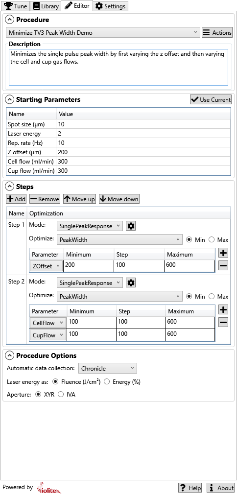
Fig. 44 The Editor tab
The Editor tab is where Procedures are created or edited. As mentioned above, TV Tuner comes with three built-in Procedures. These can be used as templates for custom tuning Procedures, but cannot be edited or deleted. Any custom Procedures that you create can be edited or deleted.
The Editor tab consists of 4 sections:
- Procedure
This section is where you select the procedure being edited. From the Actions menu, you can create new procedures, copy existing procedures, edit the name of a procedure, delete a procedure, and save a procedure. You can also import and export procedures to share with others or backup.
- Starting Parameters
This section shows the parameters that will be applied to patterns by default. You can click the Use Current button to retrieve the current values from AV2.
- Steps
This section is where you configure the parameters to be varied and their range for each step.
- Procedure Options
This section provides a few additional options for how the laser and data collection will work for the procedure.
Procedure management is done primarily through the Actions button. This button opens a menu with actions: New, Clone, Rename, Delete, Export, Import, Save Current, and Save All.
When creating a new Procedure, you will be prompted for a name. You can then also add an optional description of the Procedure in the Description field.
New Procedures initially have no Steps. You can add, remove and reorder Steps for the Procedure using the Steps section. Click the Add button to add a Step to a Procedure. The added Step will have a default name (e.g. 'Step 1'), but this name can be edited by double-clicking the name. If you need to remove a step, the Remove button can be used. The Steps of a Procedure will be run in order. You can adjust the order of the Steps using the 'Move up' and 'Move down' buttons.
The Step's "Mode" determines how the Step is analyzed. At the moment, SinglePeakResponse is the only available mode, but other modes such as 'Steady State' will be available in upcoming versions. Clicking the button to the right of the Step's mode opens a dialog to set the number of pulses to be used for each tuning ablation line within the Step, the line spacing, the spot overlap, what percentage of the peak max to use to measure the peak width, and which channel to use (Fig. 45).
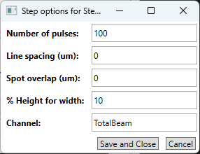
Fig. 45 The step options dialog
Note
You can modify the step options for a procedure and then right-click a procedure's step in the results tree to reprocess data that has already been collected with different parameters (e.g., to see how a different channel or % height for width looks).
The Optimize combo box selects which metric (peak width, height or area) will be optimized in the Step, and whether to target the minimum or maximum value.
The Parameter table shows the range of values, and the step size, for each tuning parameter. Clicking the button adds a parameter for tuning; clicking the button removes the selected parameter. The parameters available include: cup flow, cell flow, z-offset, fluence, spot size, and repetition rate. If a step uses 2 or more parameters, every combination of the parameters in the specified ranges will be determined.
If a Step consists of two variables, you have the option to exclude certain combinations of parameters. This can be useful if you know that certain combinations are not valid or are not of interest. To exclude a combination, click the button to the right of the parameter table. This will open a small dialog where you can click which combinations to exclude (Fig. 46).
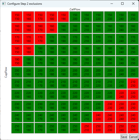
Fig. 46 The exclusions dialog
The Procedure options include what type of automatic data collection to use, whether the laser energy is specified as fluence or energy percent, and lastly whether the aperture is XYR or IVA.
fa:cog Settings
Here is the settings section
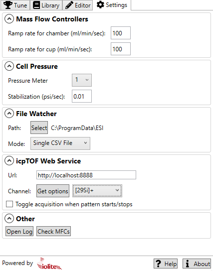
Fig. 47 The Settings tab
The Settings tab consists of 4 sections:
- Mass Flow Controllers
In this section you can configure the ramp rate when changing the cell or cup flow rate as part of a tuning step.
- Cell Pressure
In this section you can configure which pressure meter is used for cell pressure and the stabilization criteria. Stability is measured as the slope of the pressure versus time for the last 15 seconds.
- File Watcher
In this section you can configure the path to watch and the mode.
- icpTOF Web Service
In this section you can configure the URL of the web service and select which channel you want to use for SPR measurements. You can click the Get options button to connect to the icpTOF web service and determine which channels are available. You can also toggle whether you want TV Tuner to toggle TofDaq acquisition when patterns start/stop.
- Other
In this section you can find buttons to open the log file and check the mass flow controllers.
General workflow
Before using TV Tuner you should have started, warmed up, and run your typical tuning procedure for the laser and mass spectrometer. TV Tuner does not tune any of the mass spectrometer settings, so it should be as accurately tuned as possible before running a Procedure. The general workflow is as follows:
Perform any setup required for automatic data capture. See fa:cog Settings, Editor, Nu Vitesse, Tofwerk icpTOF for more information.
Place a tuning sample in the cell.
Move the stage to an area that will accommodate the tuning patterns.
Select the Procedure you want to run or create a new one. See Tune and Editor.
Create the tuning patterns. See Tune.
Verify the pattern locations are valid (e.g., don't extend beyond the sample).
Run the procedure. See Selecting and running a procedure.
Optionally watch the stabilization plot as the gas flow rates change and the cell pressure stabilizes (The Stabilization section of the Tune tab).
If using automatic data collection, browse the results as they come in (See Results).
If not using automatic data collection, wait for the procedure to finish, fetch the data, and select the data to process.
Save or share the outcome by emailing, zipping, or sending to the built-in Library. (See Actions).
Note
The Run Procedure button is replaced by a Cancel Procedure button while a procedure is running. If something does not look right while a procedure is running, you can click the Cancel Procedure button to abort.
Note
Be sure that you have calibrated the stage before running a tuning procedure. If the stage is not calibrated, the patterns will not run properly.
Other considerations
Nu Vitesse
Automatic data collection with a Nu Vitesse can be achieved by using the file watcher. In the settings, you should specify the path as a network share of the Vitesse data and the mode to Vitesse.
Note
You can export the TV Tuner pattern list for use in CoDaq by clicking the small button in the top right area of the Results section of the Tune tab.
In order for AV2 to trigger the Vitesse properly, there are some additional steps that need to be taken as outlined below:
Prepare the Hardware Connections
Verify Connector Type on Vitesse
Confirm whether your Vitesse interface uses a DB-15 connector with a screw-terminal adapter board.
If you have a screw-terminal board, you can easily connect flying-lead BNC cables.
If not, you may need to modify the existing connector or replace it to create a custom cable assembly.
Identify Required Pins on Vitesse DB-15
Input to Vitesse (from Laser SYNC-OUT): Pin 12 (+), and one of the ground pins (9, 11, or 13) as return line.
Output from Vitesse (to Laser EXT-TRIG): Pin 5 (+) for TTL out, and Pin 6 (open drain) can remain connected as instructed. Ground return also ties to a ground pin on the DB-15.
Wiring the Trigger Cables
You will create two BNC-to-flying-lead cables:
Laser SYNC-OUT to Vitesse Input:
BNC center conductor → Vitesse Pin 12
BNC shield → Ground pin on Vitesse (e.g., Pin 9, 11, or 13)
Vitesse Output to Laser EXT-TRIG:
BNC center conductor → Vitesse Pin 5
BNC shield → Vitesse open drain return Pin 6 or ground (as per instructions; typically shield to ground)
Confirm standard convention: The BNC shield is ground/return line, and center pin is signal.
Laser Side Connections
On the laser platform’s rear panel:
Connect the cable coming from Vitesse Pin 5 (output) to the laser’s “EXT TRIG” BNC. This signal triggers the laser.
Connect the cable from Laser “SYNC-OUT” BNC to the Vitesse input line (Vitesse Pin 12).
Configure Laser I/O to TTL Mode
Set Laser I/O Jumpers:
Power down the laser system and remove the top main cover.
Locate the laser I/O card (the second card from the left).
Find the I/O configuration jumpers on the top front edge.
Set both the EXT-TRIG and SYNC-OUT channels to TTL mode, following the silkscreen instructions. Both need to be in TTL mode, not switched mode.
Setup on the Vitesse
Configure your Vitesse method to accept external triggering signals. Consult the Vitesse documentation or the Nu Instruments team if needed.
Confirm the chiller control remains operational if it shares the same DB-15 connector.
Running the System and Troubleshooting
Test Triggering
With all cabling complete and both laser and Vitesse powered up, initiate a test run.
Start a batch in CoDaq to confirm that the Vitesse received the laser SYNC-OUT signal, and the laser receives the EXT-TRIG signal from the Vitesse.
Confirm Data Import and File Watcher
After a run, verify that the data files are properly created, accessible to iolite, and no import errors occur.
If errors do occur, check that you are using the latest version of iolite. If they persist, contact support@iolite-software.com.
Use TV Tuner as outlined in this document to optimize SPR.
Tofwerk icpTOF
Automatic data retrieval can be accomplished with the icpTOF web service. If this was not installed with Tof Pilot, you can download it here. You can start the web service by double clicking the TofDaqWS.exe file. You can then configure the URL that TV Tuner will connect to in the fa:cog Settings tab. You can also click the Get options button to determine which channels are available and toggle whether you want TV Tuner to start/stop TofDaq acquisition when patterns start/stop (recommended).
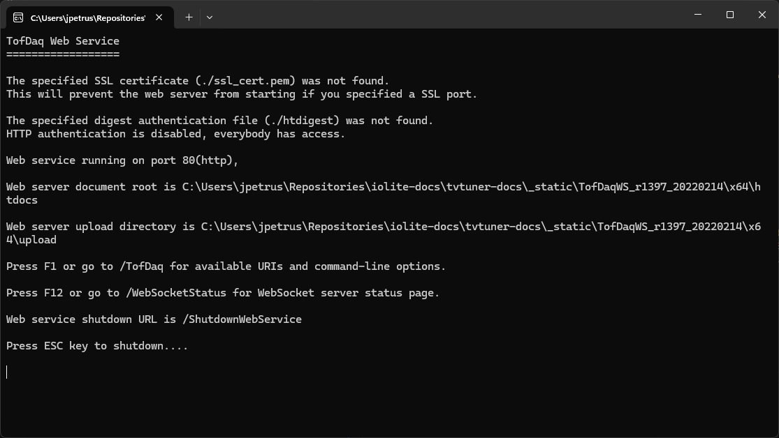
Fig. 48 The icpTOF web service
You will need to access TofDaqRec to configure the acquisition settings. Open the window from the task bar or from within TofPilot and then click the "Edit config" button.
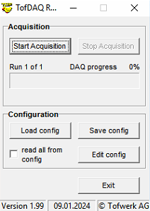
Fig. 49 TofDaqRec window
For the DAQ settings, it is necessary to use the "STICK" firmware. We also recommend that auto saving is disabled and "none" is selected for external block trigger (Fig. 50).
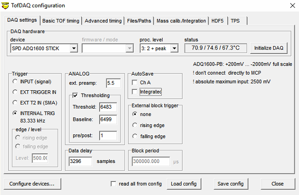
Fig. 50 TofDaqRec DAQ settings
For the basic TOF timing settings, it is necessary to increase the number of segments recorded. The settings shown in Fig. 51 worked well in our testing.
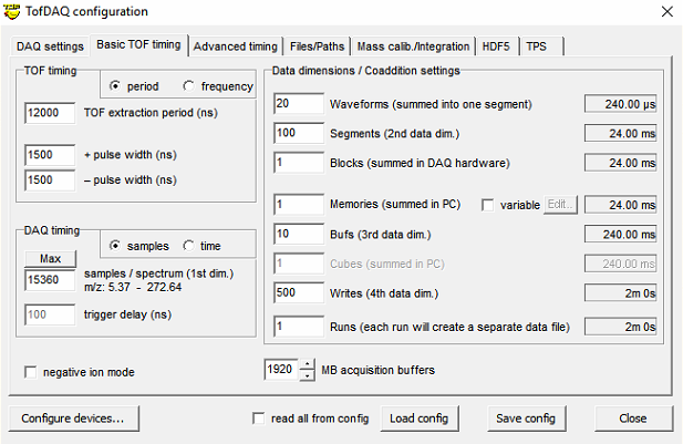
Fig. 51 TofDaqRec basic TOF timing settings
If something goes wrong
Please contact support@iolite-software.com if you have any problems. When you email, please include the TV Tuner log (can be accessed through fa:cog Settings tab), the procedure (can be exported, see Editor), and any data files that were collected. Depending on what you're having a problem with. It may be possible to zip a complete run from the actions and share that.
Email
If you want to use the email action, you will need to configure the email settings via AV2.
Peak measurements
The general peak finding and measurement system is outlined below.
Note
All operations are done on the channel specified in the step options. If you're using a quadrupole instrument, you may want to limit the acquisition to 1 analyte so that the cycle time can be kept short to achieve adequate time resolution. If using a TOF instrument, you may want to consider changing iolite's import settings such that you only consider useful channels (to avoid being dominated by a very high background channel) if using "TotalBeam".
The background mean and standard deviation are determined from the lowest parts of the data.
The expected peak locations are determined by creating a box train signal according to the rep rate and syncing it with the data.
Spurious peaks are filtered out in parts of the data where we don't expect peaks.
Peaks are found using SciPy's "find_peaks" moving backwards through intensity percentiles to see how many peaks are found.
Stop moving backwards once the expected number of peaks are found (or close to it).
SciPy's find_peaks uses a distance related to the repetition rate, height according to percentile, and rel_height according to the step options % height for width.
The information from this script is transferred back to TV Tuner for further plotting and analysis.
Support
If you have any problems, suggestions or questions, please do not hesitate to contact us at support@iolite-software.com.
Glossary
- AV2
ActiveView2, the laser control software
- CFW
Chronicle File Watcher, an application for automatically sending files from the mass spectrometer computer back to AV2.
- Parameter
A tuning parameter, e.g. the Cell gas flow rate.
- Procedure
A set of tuning Steps, executed in order to determine the best overall tuning parameters.
- Result
A placeholder or outcome of SPR analysis for a specific combination of parameter settings.
- SPR
Single Pulse Response: the typical peak measured by the mass spectrometer from a single laser pulse. Typically the SPR is described by its height (the max counts over the peak) and its width. This plugin also reports the average peak area. The width is usually described at some percentage of the max height, e.g. the width at 1% of the max height. Due to the noise associated with any one pulse measurement, these values are usually reported as the average of many individual pulses.
- Step
A part of a Procedure where one or more tuning parameters are varied to observe the effect on the pulse signal (e.g. pulse height, pulse width etc) as measured by the mass spectrometer.